Table of contents
Introduction
LiveMediaStreamer framework has been designed based on two main concepts: modularity and simplicity. Therefore, using it, a wide range of streaming applications can be designed due to its architecture. The main idea is constructing pipelines (paths and/or multipaths) of interconnected modules that process frames. Moreover, its architecture ease addition to support new audio, video, container formats and transmission protocols.
The framework has been designed for Linux platforms using C/C++ language. It’s the environment supported by all the underlying libraries:
- Live555 – Internet Streaming Media, Wireless, and Multicast technology, services, & standards
- ffmpeg – A complete, cross-platform solution to record, convert and stream audio and video
- OpenCV – Open source computer vision and machine learning software library
- x264 – Free software library and application for encoding video streams into the H.264/MPEG-4 AVC compression format
- x265 HEVC Encoder – Open source HEVC encoder.
- LAME – High quality MPEG Audio Layer III (MP3) encoder licensed under the LGPL
- Opus – Totally open, royalty-free, highly versatile audio codec
- WebM VPX – VP8/VP9 Codec SDK. A open, royalty-free, media file format designed for the web
LMS enables to use and manage platform resources with full control, which is a critical aspect for time sensitive applications.
Framework layers
In order to keep the software modular and configurable, with a simple TCP socket access API, it has been organized into three layers:
Data flow layer
The software data flow has been designed to follow the pipes and filters design pattern. In computer science a pipeline is known to be a sequence or a chain of several processors (routines, threads, etc.) placed in a manner that the output of each processor is the entrance of the next. Called pipeline thanks to the analogy to a physical pipeline. The information that flows inside a pipeline usually is a stream of records, bytes or bits that is read from a buffer or queue (pipe) by the filter (processor) that after processing it is written to another buffer to keep data flowing. Pipelines are usually implemented in multithreaded environments so it take advantage of parallel programming, so the processors may run in parallel and not in strict sequence. This is a very suitable pattern for multimedia live streaming as in such scenarios the data to process are continuous audio and video flows.
Execution Layer
The execution layer of the software is where the parallelization takes part. Each filter of the pipeline implements a Runnable pure abstract class which represents the interface between the filters and the WorkerPool class (an automated pool of workers, which has autiomatic management of threads execution). Each filter is automatically assigned inside the worker pool within a list of workers to be executed. Workers are totally independent of the pipeline composition and the filter nature, they only know about Runnables which is a simple interface that runs the processing routine of a single frame of a filter. This way independence between the parallelization and the pipeline configuration is kept. Therefore, this is an implementation of a regular thread-pool pattern where each thread consumes tasks from a task queue.
Keeping the software as a lock free implementation is important as the procedure to signal conditions between threads and awake and sleep threads might be time consuming. It may help to keep optimal usage of the CPU, but it might be waste of time, which is critical for time sensitive applications.
Moreover this approach gives freedom on how the parallelization is done and let to the management layers define the criteria to follow. Again this is important in order to determine bottlenecks and to test different criteria (i.e. audio prioritization).
Control Layer
The control and management of the pipeline prepared to be done using a self-defined TCP socket protocol so it can be managed remotely and easily presented as a cloud service as it can be operated remotely and it is pretty simple to develop web services or applications on top of it without having to actually get into the C++ code. See TCP socket API section for all the details of this protocol. The Controller class is the responsible of dispatching received events to the PipelineManager class, which is the class that has full overview of the system, it has the filters pool and their interconnections (the paths). PipelineManager class, in fact, is where execution and data flow layers meet and the Controller class owns an instance of PipelineManager.
Main classes
In the following figure there is a conceptual diagram of the logical structure of the control and dataflow layers.
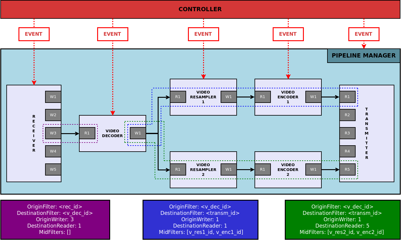
In this diagram we can see a video transcoding scenario. In this case, a video is received from the network and decoded. After that, it is encoded in two different ways with different parameters (size, bitrate, framerate). Finally, each encoded video is transmitted independently.
As it can be seen in the diagram there is a receiver and a transmitter as head and tail filters of the pipeline, respectively. Moreover there is a video decoder, which is connected to the receiver. Two video resamplers, each one connected to a video encoder, share the output of the video decoder. Finally, each video encoder is connected to the transmitter.
Three different paths form this pipeline:
The first is defined by the receiver as origin filter and the video decoder as destination filter. In this case, the origin writer must be specified because the receiver could have more than one writer. Regarding destination reader, video decoder only has one reader so it is not necessary to specify it (default id for any writer/reader is 1).
The second is defined by the video decoder as origin filter and the transmitter as destination filter. Moreover, there are two mid filters: video resampler and video encoder. It is not necessary to specify the origin writer because video decoder has only one writer. However, transmitter has multiple readers so it is important to specify a destination reader.
The third is similar to the second path. It has the same origin filter and the same origin writer. Although the destination filter is the same, the destination reader must be different (note that the writers can be shared by different paths, unlike readers).
Finally it also can be seen the PipelineManager, which contains all the filters and paths, and the Controller which manages control messages and dispatches the resulting events to the corresponding filters or to the PipelineManager.
The main structure of this approach is designed around the following 10 major classes or structures described in the following subsections:
FrameQueue
This is the pure abstract class that represents buffering structure of the pipeline. It is a circular queue prepared that owns a certain number of pre-allocated frames. It is relevant that frames are pre-allocated and reused all the time during the execution of the program, allocating memory is an expensive operation for the OS, as it implies a complete lock of the whole process memory, so keeping memory allocation and deallocation to the minimum expression is a must in order to optimize time sensitive applications.
Another important aspect in terms of optimization is that the queue must be thread safe. To avoid complex or time consuming mutex operations it have been designed in a simple lock free structure, assuming and forcing in the code single consumer and single producer scenarios.
This class is implemented by: AVFramedQueue (discret audio or video frames), AudioCircularBuffer (continuous raw audio byte array), X264VideoCircularBuffer (specific for x264 in order to tread NAL units as discrete independent frames).
Frame
This is a very simple abstract class that handles byte array of a video or audio frame and some other frame related information, such as timestamp, is planar, sequence number, etc. This class is implemented by: AudioFrame (it adds audio related data, such as sample rate, bits per sample, etc.), VideoFrame (it adds video related data, such as codec, colour space, etc.), X264VideoFrame (it adds NAL units management to VideoFrame).
BaseFilter
This is one of the most important classes, is where all the data processing is done. The most relevant elements that contains this class might be list of Readers and the list of Writers (see IOInterface description). Each filter may have from none to many inputs and from none to many outputs. Each input is determined by a single Reader and each output by single Writer. Readers and Writers job is to put in and to take out frames to and from the filter respectively. Each filter implementation must define the routine doProcessFrame, which is the responsible of processing frames given by the readers and to fill the resulting frames given by the writer with the processed data.
Another important element of filters is that they have a priority events queue. This queue stores events requested by the user in order to modify the filter configuration (frame rate, bitrate, etc.). Priority criteria is time based, events may be targeted to take place after certain amount of time (this way it is possible to program events).
Finally, the filters are responsible for connecting themselves, so it implements the connect, which connect a certain Writer from the filter to a Reader from another filter, here is where and when the FrameQueue is created and its frames allocated. Is in this connection process when the Frames and FrameQueues are initiated according to the specific data they will handle (i.e. AudioCircularBuffer for raw audio bytes or an AVFramedQueue with VideoFrames for raw video frames). The same way using disconnect routine destroy the FrameQueue that unifies two filters and destroys allocated frames. It cannot exist a FramedQueue if two filters are not connected.
This class is implemented by each processing filter of the system (audio or video encoders and decoders, receivers, transmitters, mixer, resamplers, etc.). However between each specific filter implementation and the BaseFilter class there are:
- OneToOneFilter: a filter limited to a single input stream and single output stream
- OneToManyFilter: a filter with a single input stream and several output streams
- HeadFilter: this is a filter that represents the origin of one or several streams, none inputs, i.e. the receiver filter is a HeadFilter
- TailFilter: this filter is the ending filter of a pipeline, none outputs, i.e. the transmitter filter is a TailFilter
- ManyToOneFilter: a filter that has several input streams and a single output stream, i.e. the video mixer filter is a ManyToOneFilter
Finally, it’s important to point out that there are two different types of the Filter class: Regular (main type of filter) and Server (it is an special case for network filters adapted to live555 library needs, for transmitting and receiving RTP streams).
Reader & Writer
These are two independent classes, but conceptually tightly related, because they share the FramedQueue object when connected. These are Reader and Writer objects. They are pretty simple and they only encapsulate a FrameQueue object. Each of them contain a reference of a FramedQueue, being a reference to the same object if they are connected with each other. A Writer has the routines to add frames to the queue and the Reader has the routines to read (and mark them as obsolete) frames of the queue.
Path
This class is an important object in order to determine the pipeline configuration, filters interconnections and different data paths. As the filters may have from zero to many inputs and outputs the pipeline is likely to present different branches, conjunctions and bifurcations. A Path is just a list for all the filters connected to a same branch, in fact, a Path is defined by an origin filter (HeadFilter or OneToManyFilter), a destination filter (TailFilter or ManyToOneFilter) and a sorted list of all the filters (only OneToOneFilter) sequentially connected between origin and destination filters (see Figure 1). Note that the Path doesn’t own or contain the filters; it just records their ID. The container of all the filters of the whole pipeline is the PipelineManager class. Path only stores the interconnections of a particular branch of the pipeline. The Path becomes handy when having to identify and distinguish different instances of a filter of a kind.
PipelineManager
This class as the name suggests is the class that defines the pipeline as a whole, it’s the only object that has all related information to existing filters, paths and their interconnections. Moreover it represents the contact between the data flow, control and execution layers.
In PipelineManager there are three relevant attributes: a list of Paths and a list of Filters. This class implements all the routines needed to create, destroy, assign and connect all these elements.
WorkersPool
This is a pure abstract class that is mostly in charge of executing the process method of one or several filters in a dedicated thread. Note that, in general, it’s isolated and unaware of filter type. The workers pool basically contains a list of Runnables and related C++ thread objects. A Runnable is an interface implemented by BaseFilter, which has some basic methods such as processFrame and processEvent in order to process a single frame of the filter. First processEvent is executed (the filter gets reconfigured it there was some pending event) and then processFrame (the filter process current inputs and places the result in the Writer’s queue).
When a Worker starts it runs their specific thread in an infinite loop that keeps running Runnable methods that performs specific filter actions. In order to control data consuming cadence the worker might be defined to process at a certain frame-rate, this way each iteration of its Runnable is determined by the frame-rate. If there is no frame-rate defined the WorkerPool has a best-effort behaviour, trying to consume data as fast as possible.
Controller
The controller is the class that handles the interface to outside world, it is the class that defines the control protocol. The protocol is simple, each received packet by the controller is a JSON or an array of JSONs, each JSON represents and event. There are two types of events, internal event (–ANCHOR–) or filter events (–ANCHOR–). Filter events are dispatched to the specific filter’s events queue and internal events are handled by the PipelineManager. So the controller handles the TCP listening socket and parses incoming events format and consistency.
Structures
Filters
In this section a simple description of the filters that are going to be included in the software is presented. Relevant information such as inputs/outputs, relevant parameters or tips are described using a common structured table to enable information access at a glance.
Receiver
It manages the reception of streams into the system. Supported transport protocols are RTP and RTSP.
For each input stream it creates a new writer, identified by the reception port.
| Filter name | Receiver |
| Process frame description | It manages RTP/RTSP input sessions |
| Input | Network |
| Output | Number of outputs: N Data type: codec audio/video frames |
| Parameters | None |
| Tips | For each RTP session, it creates a writer identified with the session (see Connecting filters and Path chapters) |
Transmitter
It manages the muxing and the transmission of output streams. Supported muxing formats are DASH and MPEG-TS. Supported protocols are RTP/RTSP and HTTP (only for DASH format).
Streams can be transmitted without muxing them into a container using RTP/RTSP.
It is also possible to transmit streams directly over RTP, without using RTSP to manage the session, defining the destination IP and port.
This module can have multiple readers, each one representing a stream. Each stream can be simultaneously muxed in different formats and/or transmitted using different RTP/RTSP sessions.
| Filter name | Transmitter |
| Process frame description | It manages RTP/RTSP output sessions |
| Input | Number of inputs: N Data type: coded audio/video frames |
| Output | Network |
| Parameters | None |
| Tips | Each reader can be used in many output sessions at the same time |
Video decoder
It decodes video coded frames, outputting raw video frames. It has only one reader and one writer.
Supported codecs are the ones supported by libavcodec (which includes H264, HEVC, VP8 and VP9 decoding support)
Decoded frames size and pixel format are determined by the coded frames.
| Filter name | Video decoder |
| Process frame description | It decodes the input video frame, outputting a raw video frame |
| Input | Number of inputs: 1 Data type: coded video frames |
| Output | Number of outputs: 1 Data type: raw video frames |
| Parameters | None |
| Tips | Supported input codecs: H264, H265 and VP8 Output frames pixel format and size is defined by the input frame (this module does not resize nor change pixel format, use video resampler for this). |
Video resampler
It resizes and/or changes the pixel format of raw frames, outputting resampled raw frames.
Supported pixel formats are the same supported by libavcodec (e.g YUV420, RGB24).
Configurable parameters are video output size and pixel format.
| Filter name | Video resampler |
| Process frame description | It resizes and/or changes the pixel format of the input frame |
| Input | Number of inputs: 1 Data type: raw video frames |
| Output | Number of outputs: 1 Data type: raw video frames |
| Parameters | Output size, output pixel format, discard period |
| Tips | Supported pixel formats: RGB24, RGB32, YUV420P, YUV422P, YUV444P, YUYV422, YUVJ420P |
Video encoder
It encodes raw video frames, outputting coded video frames.
Supported codecs are the ones supported by libavcodec (which includes H264, HEVC, VP8 and VP9 encoding support using libx264, libx265 and libvpx).
Configurable parameters are codec, frame rate, GoP length and bitrate.
| Filter name | Video encoder |
| Process frame description | It encodes the raw input video frame, outputting coded frame NALUs |
| Input | Number of inputs: 1 Data type: raw video frames |
| Output | Number of outputs: 1 Data type: H264 coded NALUs |
| Parameters | Framerate, bitrate, GoP |
| Tips | Supported output codecs: H264 and H265 Supported input pixel format: YUV420P, YUV422P |
Video mixer
It has multiple readers, each one associated to a channel. Its main task is composing a layout using frames of its different channels, outputting mixed frames.
It only supports RGB24 raw frames as input; output frames are also in this pixel format.
Configurable parameters are channel number and layout size. Channel configurable parameters are size, upper left corner position, opacity, layer and enabled/disabled.
It is important to consider that video mixer does not resize its input frames. This means that channel input frames and its size configuration must coincide.
| Filter name | Video mixer |
| Process frame description | It composes a layout using frames of its different channels |
| Input | Number of inputs: N Data type: raw video frames |
| Output | Number of outputs: 1 Data type: raw video frames |
| Parameters | Channel number, layout size Channel: size, upper left corner position, opacity, layer, enabled/disabled |
| Tips | Video mixer does not resize channel frames, so input frames size must be equal to channel size configuration (using video resample module) Supported input pixel format: RGB24 Output pixel format: RGB24 |
Audio decoder
It decodes audio coded frames, outputting raw audio frames. It has only one reader and one writer.
Supported codecs are the ones supported by libavcodec (e.g. OPUS, AAC, MP3). Supported sample formats are the ones supported by libavresample (e.g S16, FLT).
Configurable parameters are output sample rate, sample format and channel number.
| Filter name | Audio decoder |
| Process frame description | It decodes the input coded audio, outputting a raw audio frame |
| Input | Number of inputs: 1 Data type: coded audio frames |
| Output | Number of outputs: 1 Data type: raw audio frames |
| Parameters | Output sample rate, channels and sample format |
| Tips | Supported input codecs: PCM, PCMU, OPUS Default output configuration: 48k, stereo, signed 16bit Planar |
Audio encoder
It encodes raw audio samples, grouping them into frames and coding these ones. It has only one reader and one writer.
Supported codecs are the ones supported by libavcodec (e.g. OPUS, AAC, MP3).
Configurable parameters are output codec, sample rate, sample format and channel number. Some of these parameters may be defined by the codec, as long as the number of samples per frame (which is not externally configurable).
| Filter name | Audio encoder |
| Process frame description | It encodes the input frame, outputting the coded frame |
| Input | Number of inputs: 1 Data type: raw audio frames |
| Output | Number of outputs: 1 Data type: coded audio frames |
| Parameters | Codec, sample rate, channels |
| Tips | Default output configuration: AAC, 48k, stereo Supported codecs: AAC, PCMU |
Audio mixer
It mixes raw audio samples (grouped in frames), outputting the resulting mixed samples (grouped frames) . It has only one reader and one writer.
It has multiple readers, each one associated to a channel.
It only supports signed 16bit planar (s16p) PCM samples as input; output samples are also in this format.
Configurable parameters are output codec, sample rate, sample format and channel number. Some of these parameters may be defined by the codec, as long as the number of samples per frame (which is not externally configurable).
| Filter name | Audio mixer |
| Process frame description | It mixes input channels frames, outputting a mixed audio frame |
| Input | Number of inputs: N Data type: raw audio frames |
| Output | Number of outputs: 1 Data type: raw audio frames |
| Parameters | Channel number, master volume, channel volume Output sample rate, channels and sample format |
| Tips | Default output configuration: 48k, stereo, S16P Default mixing channels: 8 |
Demuxer
It is a wrapper of the ffmpeg framework which enables LMS to receive all supported input network protocols by ffmpeg. It is designed as the receiver filter, it is a Head filter.
It receives streams from the configured input URI (i.e.: RTMP, …) and outputs its media streams to the following filters (usually an audio or a video decoder). So, it has multiple writers each one associated to each output stream.
Configurable parameters are the input URI.
| Filter name | Demuxer |
| Process frame description | It manages input network sessions |
| Input | Network |
| Output | Number of outputs: N Data type: codec audio/video frames |
| Parameters | Input URI |
| Tips | For each stream associated to input URI, it creates a writer |
Dasher
It is a Tail filter as it is the transmitter filter also. It is configured with different input streams (audio and video) which are encapsulated to MPEG-DASH.
It has multiple readers, each one associated to a dasher segmenter. Resulting outputs (MPD, init and segments) are stored in previous defined system folder path.
It supports H.264 and H.265 as video input codecs and AAC as audio input codecs.
Configurable parameters are input codecs associated to each input stream which are also associated to a dasher segmenter. The duration of the segments, the maximum number of segments and minimum buffer time are also input configuration parameters. Output parameters are the destination folder and the files base name.
| Filter name | Dasher |
| Process frame description | It manages MPEG-DASH stream encapsulation and file creation |
| Input | Number of inputs: N Data type: coded audio/video frames |
| Output | MPEG-DASH files (MPD, init and segments) to be served through an HTTP server |
| Parameters | Segment duration, maximum number of segments, minimum buffer time, destination folder and files base name |
| Tips | Each reader is associated to a segmenter |
Pipelines
A pipeline is defined by a group of paths and its associated filters which process media frames. Its head filter is always a receiver or a demuxer, which is capable of capturing network streams and feed different filters with the received data. Its tail filter is always a transmitter or a dasher, which is fed by different filters and is responsible for muxing this data and sending it to the network. Between them, each filter process its input frames and feeds the filter/s connected to it.
Different pipelines correspond to different use cases. For example, a transcoding scenario is described in –ANCHOR–. Another example could be a video production scenario, using video mixer and audio mixer filters along with encoders, decoders and resamplers.
Connecting filters
Filters need to be connected between them in order to create a useful scenario.
Filters are connected using frame queues. Each filter consumes frames from its input queue/s, processes them and feeds its output queue/s with these processed frames.
Regarding this, there are four types of connection:
- One to one: filter A output is connected to filter B input
- Shared output: filter A output is connected to various filters, which share output frames. This means that the same frame is read by many filters at once concurrently.
- Many to one: many filters are connected to different inputs of the same filter, which must support multiple inputs (e.g audio mixer, video mixer)
- One to many: many filters are connected to different outputs of the same filter, which must support multiple outputs. The difference between this and “Shared output” connection is that in this case the different outputs represent frames with different information (e.g. a video splitter, where each output represents a part of a video frame).
Paths
A path represents a series of one to one connections between filters. It is defined by:
- Origin filter: path head filter ID
- Destination filter: path tail filter ID
- Origin filter output: head filter writer ID (if origin filter supports multiple outputs)
- Destination filter input: tail filter reader ID (if destination filter supports multiple inputs)
- Middle filters: filter IDs between head and tail (head-to-tail ordered). These filters must only have one input and one output.
Management
There are two management levels in order to control the whole system at real-time
TCP API
The system core works using a TCP socket communication system based on JSON messages exchange. The system is listening to a specific TCP port, waiting for new connections. For each connection, the system waits for a JSON message that can be composed by many event JSONs.
An event JSON message contains:
- action: the method/action to be executed
- filter_id: the id of the filter associated to the action (0 if internal event)
- delay: the execution delay
- params: parameters involved in the action
Each event JSON is parsed and an event is created using its information. Events are pushed to the corresponding filter event queue and executed by delay order. However, some events correspond to general management events (internal events), so they cannot be executed by any filter specifically. These events are identified by filter_id and are executed by the PipelineManager.
A JSON describing possible errors (if any) is sent as response.
HTTP REST API
The remote management is achieved using a web framework middleware, which manages HTTP REST requests transforming them to TCP socket management messages (core events) to the LMS instance to work with.
A REST request can involve more than one core event. In this case, the system core management message is formed by a list of event JSONs, each corresponding to an event. This way multiple events can be transmitted at once and facilitate higher level events implementations, for instance, there could be a predefined event in the middleware named reduceQuality which could be composed by multiple core events configuring multiple filters such as the Video resampler and the Video encoder.
It’s important to note that the middleware as it implements a RESTful API it is developed using more web appropriate technologies, which are Node.js and the Express.js framework. This is important as the implementation of this middleware becomes easy to develop, maintain and extend with other possible higher level events. So this is really easy to adapt and customize to a specific use case or high level application needs, without even having to modify the core software.
Moreover this middleware is responsible for starting and stopping the core binary.